Warning: "continue" targeting switch is equivalent to "break". Did you mean to use "continue 2"? in /home/choste/public_html/press/wp-content/themes/suffusion/functions/media.php on line 669

Warning: "continue" targeting switch is equivalent to "break". Did you mean to use "continue 2"? in /home/choste/public_html/press/wp-content/themes/suffusion/functions/media.php on line 674

Warning: "continue" targeting switch is equivalent to "break". Did you mean to use "continue 2"? in /home/choste/public_html/press/wp-content/themes/suffusion/functions/media.php on line 687

Warning: "continue" targeting switch is equivalent to "break". Did you mean to use "continue 2"? in /home/choste/public_html/press/wp-content/themes/suffusion/functions/media.php on line 692

Warning: "continue" targeting switch is equivalent to "break". Did you mean to use "continue 2"? in /home/choste/public_html/press/wp-content/themes/suffusion/functions/media.php on line 697
Project Proposals » UnRulyRecursion » Page 4
Mar 072012
 

Problem Statement

Limited build space for 3D plastic models is the current limitation of Open Source 3D printing.  Systems like RepRap, Makerbot, and Ultimaker have made such significant improvements in the print quality, speed and reliability in the last year, that the size of the printable space is becoming one of the bigger constraints.  A particular application for such large print space is building parts for model airplanes.  These parts require very light weight from minimal infill, and the strength of being built as a single part.  Slicing the parts into multiple pieces for separate printing is not appropriate for these applications.

Design Solution

I have already begun building a very large format 3D printer to experiment with printing large parts, but the cartesian robot is not complete and needs funding to finish development.

  • The projected print space of this 3D printer is 10 inches by 10 inches by 22 inches tall.
  • The cartesian robot will use precision ground rods and linear bearings similar to the Makerbot and Ultimaker.
  • My broken motherboard needs to be replaced with a current generation Makerbot motherboard
  • The MK3 extruder needs to be updated to use a more current plastic motor adjustment and perhaps a stepper motor or feedback mechanism

Completion Overview

This project should be easily completed by the end of the semester, and be printing parts in the Invention Studio.  I would be willing to leave it in the invention studio for other people to use until the 3mm plastic is used up, or two semesters.  Afterwards, I would also be willing to print items for the studio from home, provided I am compensated for the plastic.

Bill Of Materials

Item Unit Cost Qty extended
Makerbot 3/8″ linear Bearings $15 (4 bearings) 3 $60
36×3/8″ Precision Shaft A 7X 1-1236A $29 4 $116
16×3/8″ Precision Shaft A 7X 1-1216A $13 6 $78
MakerBot Motherboard v2.4 $85 1 $85
Arduino Mega $65 2 $65
Total $404
Mar 072012
 

Here is where additional info will be posted for the project. Currently all info that we do have is in the below-pasted proposal, and past experience designing and building a lightsaber hilt.


Maker’s Club Seed Money Proposal


Lightsaber Construction Quest


What is It?

The idea is to make a Lightsaber that is suitable for using as a dueling prop. The project entails machining an aluminum bar stock to the correct internal dimensions to fit the blade, as well as to be aesthetically pleasing (AKA awesome looking).

Origin:

Devon and I have been very interested in fan videos and spinoffs of the Star Wars series since we first watched it. Indeed we have produced a few videos inwhich we wield the iconic weapon in an attempt to destroy eachother. It has been a lot of fun so far, but we would like to step it up to the next level (being that of Ryan Wieber, who lead the charge in fan-made lightsaber videos). Quality props would allow us to increase the realism of the scenes as well as reduce the number of props needed due to breakage.
Design and Considerations:

The general construction philosophy is based of Ryan Wieber’s Novus at www.sabershop.com (and his carbon fiber blade will be used for the blade itself). Techniques will be drawn from the many sabers created at www.slothfurnace.com. We plan to use the lathe and mill to shape the aluminum into the hilt, and create a pin mechanism to hold the carbon fiber blade steady against the inside of the hilt. It will be important to not have sharp edges around the lip of the hilt so as to reduce fatigue and chance of breakage of the blade. We also plan on machining the hilt in several interlocking parts such that shock absorbing o-rings can be used on the inside to extend the life of the blade itself.

Skills Needed:

The main skill needed in this project will be operation of the lathe. It will be important to have knowledge of how to safely use the lathe to create the shapes that we create. A secondary skill will be use of a CAD package in order to have an idea of how we want the lightsabers to look. Additionally, with interlocking parts the solid models will be useful for guaranteeing the feasibility of the interaction. One thing that Taylor brings to the project is the experience of using a lathe to make a similar prop (also out of aluminum, but for a different size blade), and can guide the process down the right path.

Bill of Materials:

Item Quantity Approximate Cost
Aircraft Aluminum 6061
(9056K273 Mcmaster Carr)

3 ft

$45

Carbon Fiber Blade (SaberShop)

2

$72

Assorted Rods, paint,  and other trinkets

$53

Total

$170


Goals and Scope:

This project is fairly simple in its setup (requires us to model the lightsaber in CAD). Realistically this project can be complete in about two weeks, so We could have some really cool props to show off by the end of the semester, even if we take a little longer than two weeks to finish.

Mar 072012
 

Here is where additional info will be posted for the project. Currently all info that I do have is in the below-pasted proposal, and past experience designing or building computer cases.


Seed Grant Proposal

Computer Case Project

What is It?

The computer case project is just that, a case that will be laser cut from Lexan that will house a minimal computer, (m-Atx motherboard and smaller) with the intention of being an attention-grabbing set-top box/front-end for a media setup.

Origin:

This project is actually not original, but was inspired by a project I stumbled across on Ponoko (a mail order laser cutting service) that was submitted by another user (project page here: http://www.ponoko.com/design-your-own/products/mini-itx-computer-2078). This immediately struck me as a (fairly) unique case that can be modified and personalized by the user. This along with the design challenges of organizing and anchoring the components in a logical manner are what fuels my motivation.

Design and Considerations:

I have designed lexan cases in the past, however have never actually built one. The limited factor was indeed the cost of the laser cutting service. I will have to design this case from scratch, but have worked extensively with computer components, so it will not take long. Some considerations that I will take into account include: ample cooling, and slide in assembly/mounting of drives.

The case will probably hold the following: m-Atx motherboard/cpu/RAM, a power supply, an SSD OS drive, an HDD high capacity storage drive, a slim ODD, and several case mounted fans.

Skills Needed:

The skills needed to build this project include a knowledge of SolidWorks or another CAD package in order to construct the model. I will also need to make sure I am taking accurate measurements of the components. All told, intelligent design will be the most important skill, and basic assembling will be secondary.

Bill of Materials:

Item Store Approx Unit Price Qty Total
Acrylic (colored) (open to advice)

$30

4 (24”x24”)

$120

Assorted Hardware Home Depot

$15

$15

Total

$135

Goals and Scope:

The goal of this project is to have a complete case before the end of the semester. Ideally it would be done far before that. I would estimate the cutting time to within a few hours, and the assembly time to something similar. The bulk of the time to be put into this project is in the design of the case. It is entirely possible for me to design this case over the next few weeks and have it ready to go beyond that. Another benefit to this project is that I can make my files available to anyone who is interested duplicating the project, or possibly even working with someone who would like to adapt the idea to their own setup (or a computer in the lab!).

More Information:

More information is be available upon request, and may be available (if I have time to put it up…) at http://unrulyrecursion.com/press/2012/03/computer-case-project/

Mar 072012
 

Updated: March 11, 2011


Here is where additional info will be posted for project bedloft. Currently all info that I do have is in the below-pasted proposal and a dropbox folder of mine, which includes things like justifications for board calculations and what-not.


Files

Initial Hand Sketch

SolidWorks Generated BOM (not formatted wonderfully)
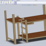
SolidWorks Model


Currently Unimplemented Features

Not Hand Drafted
-Plywood insert to allow bed in upper
-Side Attachment (bed-size)
–Built in bedside table
–Built in desk under attachment
–Hinge Down extension to accomodate a bed
—Hinged (to vert. supports) support for bed
-Hinged/Fold over cover to allow additional desk space
-Sway Bracing

Change
-Bottom Platform to be more low waste and compact
–No plywood, 2×4’s and 1×4’s for slats,
(two assemblies that mate)
–Not attached to rest of loft (has own legs),
but does mate with it (slats overhang 2×4’s of loft)


Pictures


Seed Grant Proposal

Project BedLoft

What is It?

Project BedLoft is exactly that: a lofted bed that supports up to a queen size mattress. Other amenities that it has includes a desk space for two, and the option for the seat to be covered to make all the space on top storage space. Additionally there is space under the bed for small things to be stored.

Origin:

I conceived of this project to solve the problem of a cramped living space. Like most college students, I am mostly confined to one or two rooms wherever I am (currently I am off campus), and my room is generally stuffed full of my stuff. Building a way to utilize currently unused space would greatly help organize the room and lower stress levels (being stressed when things are overly messy).

Design and Considerations:

I designed this about a year ago, when I was in a different living situation (a coop apartment in South Carolina) that was very small. The bed size was chosen based on what mattresses I already had. The addition of the desk was something that I thought was cool, and would be a place where I could set up my computer(s) and be able to have them correct no matter what other furniture is available to me. In designing the desk, and the rest of the bed, there was a lot of visualization to get the right dimensions/proportions, and some searching online to find how professionals do things (like the height from the desk chair to the desk surface ~ 10 inches, by the way). Another feature of the bedloft is how easily it can be taken apart for storage or transportation. I designed it to break down into small pieces that were mostly flat such that it could be transported to and installed in a new place relatively easily. One would only need break it down and move the pieces, instead of try to finagle a huge mattress frame through hallways and doorways. The hardware holding it together is designed as lag bolts and t-nuts, which would make it easier to disassemble and reassemble, and most are designed to be the same type, so it is hard to use hardware in the wrong place.

Skills Needed:

The skills needed to build this project include a knowledge of SolidWorks for manipulating the current model to ensure it meets the requirements of my current living space, and to use as a template and guide for construction. Beyond that, I will need to be able to safely use a variety of power tools including (but not limited to) a miter saw, a table saw, and a drill press.

Bill of Materials:

Item Store Approx Unit Price Quantity Total
2×4 lumber (stud) Home Depot

$4

20

$80

2×6 lumber Home Depot

$5

6

$30

4’x8′ Plywood Home Depot

$25

3

$75

5/16th Lag Bolts Home Depot

$40

1 (box 50)

$40

5/16th T-Nuts Home Depot

$1

14 (4 pack)

$14

Forstner Bit
(if needed)
Home Depot

$11

1

$11

Total

$250

Goals and Scope:

This project could easily be done in less than a week, given all day every day to work on it. However, with my time constraints, coupled with finding a ULI to work in there with me, I would overestimate the project to take a month, which would be before the end of the semester. I would likely be able to take advantage of lab hours on most Tuesdays and Thursdays.

More Information:

More information is be available upon request, and may be available (if I have time to put it up…) at http://unrulyrecursion.com/press/2012/03/project-bedloft/