Mar 272012
 

I recently had the opportunity to design (and have fabricated) a sheet metal chassis for my Fender 5E3 clone guitar amp. I was given a few hints about what things were possible with an industrial press brake, but until I watched the parts get fabricated, I had never actually seen a serious vertical press brake. I learned quite a bit about how a skilled brake operator can fabricate beautiful parts even when the designer was clueless or negligent.

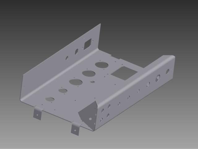
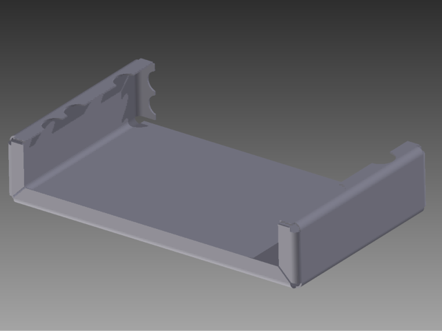
The following renderings of the sheet metal parts show the ubiquitous amount of features incorporated into the two parts, which was necessary for the compactness of my overall design (remember, I’m trying to squeeze a full size 1×12 combo amp into a practice amp format).

Many of these features are problematic, both when attempting to draw the feature, and when the brake operator was trying to bend the parts. Perhaps they are hard to draw, because programming the CAD tool to do something that is difficult to manufacture is not a priority!

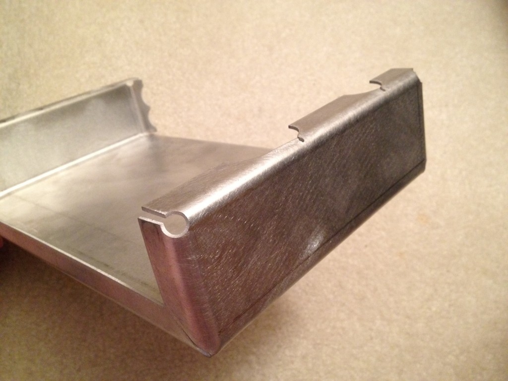
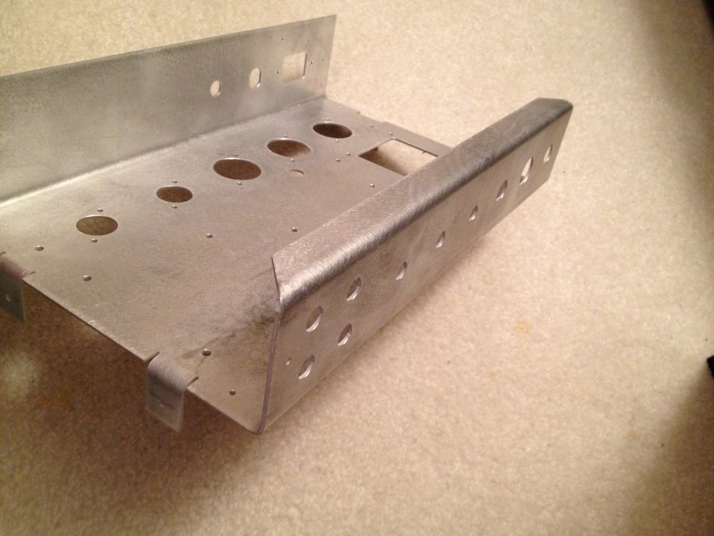
The biggest issue with my design was features that were too close to the bend. Anything that is not perpendicular to the bend is subject to “roll out” according to the operator. He managed to beautifully bend several problematic flanges by using a “backing plate” technique. Not sure if that is an official term, but basically it amounts to bending the real part against the die, and having a support piece of sheet metal underneath it to make the weird features bend properly. You can see the difference between a normal bend and a backing plate bend by looking for the absence of the U-block tool mark, a slight discoloration line running parallel to the bend.

The two small holes in this part are defects from the water jet fabrication, not actual features in my model.

With this tooling mark, we can actually determine how to avoid the backing plate problem, which simplifies the fabrication of a one-off part considerably. The mark is .445 inches from the outside of the adjoining section, so the minimum safe bending flange length is .5 inches for my Aluminum 2024-T3 .062 thickness sheet at the minimum bend radius of 3/16″. Turns out, my 3/4″ flanges were a good safe length before cutting features out of them.

In the end, it took about two hours total to bend both parts, but it could have been twenty to thirty minutes if the flanges had been much simpler. I had been thinking that I wanted to the box to help shield circuit from RF noise as much as possible, but considering the old enclosure had negligible noise and negligible shielding the extra flanges are probably a waste.

Lessons Learned

  • Avoid features that are not perpendicular to the bend near the bend radius. This includes angles, holes, circular cutouts, and other assorted odd features. These features actually are permissible, but should really be machined into the flanges after bending if at all possible.
  • Make sure your flange lengths are long enough for the press brake to operate on them without a backing plate. This may be a guess in many cases, but a conservative guess is better than nothing.
  • Use the minimum bend radius for the material you are using, unless there is a specific need otherwise. Many less skilled operators will ignore the drawing and default to the minimum bend radius chart for bending their parts.
  • Call out every bend radius on your drawing. Do not leave these as a default, you might forget what you designed, or the operator may have to try and read your mind. If the operator uses the wrong die, your part will not come out the correct size and shape!
  • Call out every flange length length and wall size on your drawing directly. Use reference dimensions if this involves over-dimensioning the part. (Hmm, can you guess why I decided that was a good idea? Do you really want the brake operator to be doing math in order figure out to bend your part?) Forget about your high school drafting class exercises, nobody wants spend time doing that in industry, and it makes the fabricator mad at the designer for ignoring his needs.
  • Call out as many permutations of dimension on your flat pattern as you can think of, even if many of them are reference only. (Same thoughts as the previous bullet!)
  • Avoid designing so many flanges that you have flanges meeting at a corner. It is really not a big deal when you are getting a large number of the part fabricated because the brake operator can justify cutting a die to the appropriate length. Unfortunately, this is typically cost prohibitive for one-off jobs. I got lucky because the brake operator had some appropriate custom dies laying around from other volume jobs recently run in the shop.

One additional item worth mentioning: machine calibration is rarely perfect. My brake operator was able to bend my parts with almost extreme precision, but he had to set up each type of bend with 3 or 4 test attempts before attempting to brake the actual part. If the machine readout was perfect, then he could have just punched in the numbers and bent the part. The operator had experience with the machine, and knew not to trust the readout without testing it, so my parts were not ruined, but that is why you should put as many dimensions on the flat pattern and folded views as possible. You really do not want to force the brake operator to be guessing or doing math on your part, that is what engineering is for!

I know I mentioned this before, but I really cannot stress it enough, DIMENSION EVERYTHING! Most machinists or machine operators did not make quite the grades you did in their math classes, and even if they did, you are trusting someone else to figure out something that you already know. Don’t be stingy, just tell them and you will get your parts back faster and cheaper!

NOTE: In my case, the parts I designed were being fabricated on a press brake, using the air bending technique illustrated in the video and the bottom image on that wikipedia page. If you believe wikipedia, the Sheet Metal page has some additional info, indicating that the bend radius is a function of the width of the lower U-block, V-block, or Y-block, but my inner radius was 3/16″ and die radius used in the brake was also 3/16″.
Mar 072012
 

Design Problem

There are several situations, both at home and in the Invention Studio, that could benefit from dust removal.  In particular, the laser cutter air filters would last much longer if the dust was separated from the air before the air is filtered.  The belt sander and band saw could avoid spewing quite so much sawdust into the air if the dust collection ports were utilizing a dust separator to capture the sawdust.  Sawdust collected from these places does not get inhaled nor need to be cleaned off of the floor.

Design Solution

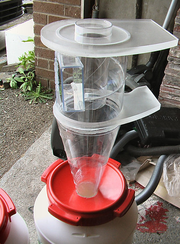
A cyclonic dust separator can collect low or high volumes of dust from the air.  Small versions of such cyclonic separators can be operated from a relatively large shop vacuum, although medium sized cyclonic separators require a custom brushless motor and controller to operate efficiently.  The designer of the spreadsheet calculator for this project claims his 6 inch version is measured to provide 99.9% separation efficiency on particles sized under 5-microns.

http://billpentz.com/woodworking/cyclone/cycloneplan.cfm

Bill Pentz’s Cyclone Worksheet

Cyclonic Dust Separator Demonstration

Here is a better view of the apparatus:

Dust Sniper 6 inch Cyclonic Dust Separator

Bill Of Materials

Item Unit Cost Qty extended
McMaster 3″ Acrylic Tube 8486K367 $24 1 $24
McMaster 6″ Acrylic Tube 8486K397 $29 1 $29
12x12x1/2″ Acrylic Sheet 8560K265 $30 2 $60
48x48x.060″ Acrylic Sheet 8560K177 $42 1 $42
Total $155
Mar 072012
 

Problem Statement

Limited build space for 3D plastic models is the current limitation of Open Source 3D printing.  Systems like RepRap, Makerbot, and Ultimaker have made such significant improvements in the print quality, speed and reliability in the last year, that the size of the printable space is becoming one of the bigger constraints.  A particular application for such large print space is building parts for model airplanes.  These parts require very light weight from minimal infill, and the strength of being built as a single part.  Slicing the parts into multiple pieces for separate printing is not appropriate for these applications.

Design Solution

I have already begun building a very large format 3D printer to experiment with printing large parts, but the cartesian robot is not complete and needs funding to finish development.

  • The projected print space of this 3D printer is 10 inches by 10 inches by 22 inches tall.
  • The cartesian robot will use precision ground rods and linear bearings similar to the Makerbot and Ultimaker.
  • My broken motherboard needs to be replaced with a current generation Makerbot motherboard
  • The MK3 extruder needs to be updated to use a more current plastic motor adjustment and perhaps a stepper motor or feedback mechanism

Completion Overview

This project should be easily completed by the end of the semester, and be printing parts in the Invention Studio.  I would be willing to leave it in the invention studio for other people to use until the 3mm plastic is used up, or two semesters.  Afterwards, I would also be willing to print items for the studio from home, provided I am compensated for the plastic.

Bill Of Materials

Item Unit Cost Qty extended
Makerbot 3/8″ linear Bearings $15 (4 bearings) 3 $60
36×3/8″ Precision Shaft A 7X 1-1236A $29 4 $116
16×3/8″ Precision Shaft A 7X 1-1216A $13 6 $78
MakerBot Motherboard v2.4 $85 1 $85
Arduino Mega $65 2 $65
Total $404
Mar 072012
 

A Proposal by Sterling Peet

Problem Statement

I have a cat that is terrible at using the litter box. I have a taken measures including using a litter box with a top and purchasing quality, scented, clumping kitty litter to help combat the issues, but the current situation is not sufficient. My cat does not understand the concept of burying her business, and thus my closet routinely smells like a small animal graveyard. Due to the configuration of my closet, bedroom, and other living arrangements, this aroma saturates my bedroom, and this is unacceptable.

A secondary complaint about my cat concerns her weight. That is, she has too much of it. She is fat. The solution for this is to feed her a measured amount of food, rather than just topping off the bowl all the time. Unfortunately, this also means she will wake me up in the morning to be fed, and I need to be available to feed her on a regular schedule. This is not compatible with my school schedule, so I want to build an automatic dispenser that can feed her the allotted amounts at appropriate times.

Project Requirements

The Primary goal is to exhaust the egregious odor out of the window in my closet [no, I don’t know why my closet has a window, but it makes a convenient place to pierce the brick wall for ventilation].

The opened window also needs to be discreet from the inside, the opening must be [mostly] only exhausting air, and located behind some piece of furniture to obscure and otherwise plug the opening.

The cat does not like having a gale force breeze blowing between her legs while using the litter box, so the exhaust fan must be controllable, preferably variable speed, and be able to sense the cat’s presence.

Secondary requirements include being able to feed the cat without needing human intervention on school days, a water dish with an overflow tray and catch bottle (she is a messy drinker), a remote administration and monitoring interface, and a place for the cat to play or look out the window. Additionally, the closet has ethernet, but not 110 AC.

Design Solution

To solve the primary problem and satisfy the design requirements, I plan to build a wooden cat tree to house the litter box, automated feeding bowl and water dish, cover the opening in the window, and contain a fan loaded exhaust duct. The duct will have a louver that closes when the fan is not blowing, in order to keep out critters and weather when not in use. The cat feeder and fan blower will be arduino based custom embedded circuits, and to provide reliable and maintenance free power and communication, the project will use a simple ethernet communication protocol and power over ethernet for the power supply. The fan circuit will employ an IR motion detector similar to those used for automatic doors to detect the cat entering and exiting the litter box.

Skills Summary

All of the skills required for this project are either skills in which I am already proficient, or I know that I am within reasonable reach of obtaining. The planning will require a drafting skills in Autodesk Inventor for the mechanical and EagleCAD schematic capture and board layout skills for electrical aspects. I have already proto-typed an arduino circuit that checks an IR motion sensor and appropriately controls a computer case style fan. The power over ethernet aspect is something that I wish to learn about, but I have a contact in the GT GVU that has down POE design, and I have already convinced him to teach me about it. The final aspect of this project requires programming skills, making this a particularly cross-discipline project.

Project Completion

This project is one that I feel is within reach of completing by the end of the semester. The most unlikely parts to complete are the final electronic assembly and programming, but the design of the electronics would be complete; with parts and circuit boards on order. The plan will be to start with the mechanical design of the cat tree to accommodate the litter box, exhaust duct, window opening, external vent louvers, and physical interface for the cat feeder and water bowl. Next the final fan control electronics will be developed, followed by the POE and ethernet communication interface. Finally, the feeder and water bowl will be developed along with the associated electronics. The only portion that I feel is questionable to complete by the conclusion of the semester is feeder and water bowl electronics, and again, this would be a result of waiting on circuit boards and parts to arrive.

Bill Of Materials

Item Unit Cost Qty extended
2x2x4′ $3 6 $18
3/8″ Plywood $20 1 $20
Fans $10 2 $20
Custom Fan Control Circuit $40 1 $40
Arduino $35 2 $70
Custom Power Over Ethernet Circuit $50 1 $50
IR Motion Sensor $10 1 $10
Custom Cat Feeder Circuit $40 1 $40
Cat Feeder NEMA17 Stepper Motor $20 1 $20
Total $288