Warning: "continue" targeting switch is equivalent to "break". Did you mean to use "continue 2"? in /home/choste/public_html/press/wp-content/themes/suffusion/functions/media.php on line 669

Warning: "continue" targeting switch is equivalent to "break". Did you mean to use "continue 2"? in /home/choste/public_html/press/wp-content/themes/suffusion/functions/media.php on line 674

Warning: "continue" targeting switch is equivalent to "break". Did you mean to use "continue 2"? in /home/choste/public_html/press/wp-content/themes/suffusion/functions/media.php on line 687

Warning: "continue" targeting switch is equivalent to "break". Did you mean to use "continue 2"? in /home/choste/public_html/press/wp-content/themes/suffusion/functions/media.php on line 692

Warning: "continue" targeting switch is equivalent to "break". Did you mean to use "continue 2"? in /home/choste/public_html/press/wp-content/themes/suffusion/functions/media.php on line 697
Sterling » UnRulyRecursion » Page 3

Sterling

Computer Science student at Georgia Tech

May 252012
 

Motivation

I tend to have at least three different sound sources running on my desk, usually computers.  Only one will be playing music, but I do want to get the audible notification noises from all of them at the same time.  Additionally, I don’t want to suck up valuable bandwidth on the network with network based audio.  On top of that, I want at least one of the computers to be able to adjust the receiver, so the control side of this includes automated volume and preferable tone controls for everything that can be adjusted both manually and remotely.

Project Requirements

  • 4 stereo inputs
  • 1 master send/receive (effects loop before the master fader)
  • RCA/Dual Phone/Stereo Phone/stereo line inputs
  • No individual tone circuits, but leave lugs/terminals to add them later
  • Each channel selectable (or mutable)
  • No Phase inversion between input/output
  • Master balance control
  • Individual channel gain trim (this would be a trimpot, not normally adjusted)

Preferred Features

  • Direct Injection for Hi-Z musical instrument
  • Turntable/RIAA circuit accommodation
  • 48V phantom power
  • Individual balance control
  • Relay and aux 110V outlets, for controlling an external power amplifier
  • Rack mountable case
  • Network enabled

Resource Links for the Mixing Receiver

http://www.generalguitargadgets.com/diagrams/mixer_sc.gif
http://sound.westhost.com/project30.htm
http://sound.westhost.com/project35.htm
http://sound.westhost.com/project94.htm
http://sound.westhost.com/project94a.htm
http://www.sparkfun.com/products/10976
http://www.sparkfun.com/products/9117
http://www.sparkfun.com/products/10595
http://www.arduino.cc/
http://www.pjrc.com/teensy/
http://leaflabs.com/devices/maple/
http://www.mouser.com/ProductDetail/Microchip-Technology/MCP4651T-103E-ML/?qs=sGAEpiMZZMsX%252bY3VKDPZyLVlvg2cCMxnSx6ZDqRJwfM%3d

Apr 022012
 

I have been doing some research on archtop guitars and luthierie, because I would like to build myself an electric archtop semi-hollow guitar.  Being that I believe all reasonably modern fabrication usually involves CAD, I have been trying to model the guitar in Autodesk Inventor.  With any luck, I can avoid becoming a master craftsman at woodworking and use CNC techniques to fabricate my guitar with pretty good quality.

Archtop guitars are just what they sound like, Arch-topped!  So, unlike your flat-topped acoustics that most people think of, we have a side profile of the guitar front (and back) that is not flat.

The trick was, I did not know what the shape of that arch really is, which is important to being able to model it.  I did have a topo map of the guitar top on the plans, but I do not really trust it.  It might be sufficient if one is only using hand tools and simpler power tools, to fabricate the guitar, but I am going all out modern CNC.

The Curtate Cycloid

After googling around a bit, I discovered this picture, showing this shape is a curtate cycloid.  A regular cycloid line is formed by drawing a line from a point on a circle while rolling the circle along a straight line.  Unlike the regular cycloid, a curtate cycloid is formed by drawing a line from a point on a smaller, concentric circle inside the larger rolling circle.  Mathworld has a really good graphical explanation of how it works:

After watching that neat gif for a few minutes, it becomes readily apparent why Cremonese violin makers would choose this shape, the geometry is easy to draw.  I found a tool for generating the shape, but its meant for printing out templates, not for adding to a CAD drawing.  I have recently read that Autodesk Inventor 2013 has a new feature allowing mathematically defined equation curves, but since I just got 2012 installed, I think I will put that off a bit.  Instead, I created a spreadsheet to generate points for a spline in Inventor.  The math is pretty simple, read about it on the Mathworld website.

Download the Spreadsheet: CurtateCycloid

F-Hole Geometry

I had previously thought that the shape of the F-hole was largely an aesthetic thing, and I didn’t care to particularly for the shape of the F-hole on the set of plans I have.  So I thought, “gee, maybe I can look up some F-hole placement and geometry and find something I like.”  Well, to my surprise, the shape and position are apparently quite effective in shaping tone, but the method of determining the best shape is largely empirical.  Since I am not really interested in the PhD level research involved for analyzing sound hole shapes, plus my guitar is semi-hollow and electric, perhaps it is a bit less critical.

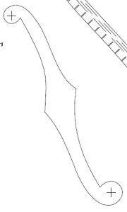
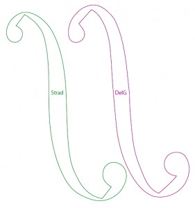
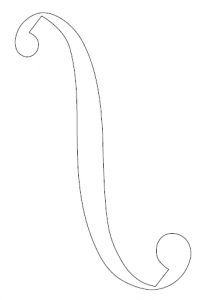
I tend to like the Stradivarius shape, but I also like the diamond in the middle of the original pattern.  I will probably combine them to get a design I like for my guitar.  For comparison, here is the Gibson ES335 shape, the Stradivarius, Del Gesu, and Baumgartner F-hole hapes.

This really awesome violin building forum thread is where I got most of the links and info on cool F-hole stuff:

Maestronet Forum Thread

For Reference, I bounced through these interesting sites while trying to figure out how to model an archtop guitar:


Mar 272012
 

I recently had the opportunity to design (and have fabricated) a sheet metal chassis for my Fender 5E3 clone guitar amp. I was given a few hints about what things were possible with an industrial press brake, but until I watched the parts get fabricated, I had never actually seen a serious vertical press brake. I learned quite a bit about how a skilled brake operator can fabricate beautiful parts even when the designer was clueless or negligent.

The following renderings of the sheet metal parts show the ubiquitous amount of features incorporated into the two parts, which was necessary for the compactness of my overall design (remember, I’m trying to squeeze a full size 1×12 combo amp into a practice amp format).
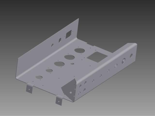
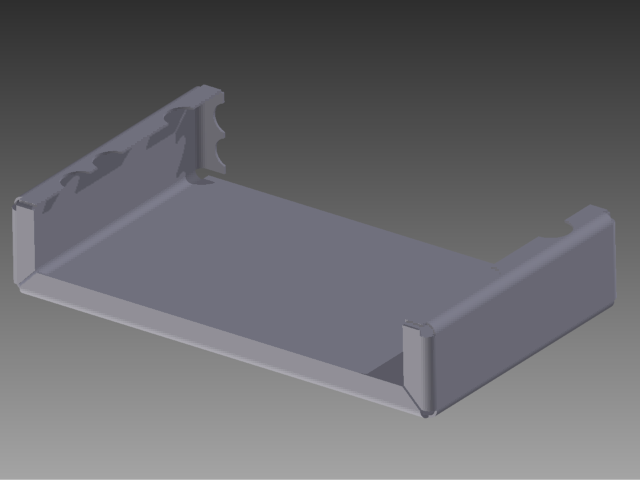
Many of these features are problematic, both when attempting to draw the feature, and when the brake operator was trying to bend the parts. Perhaps they are hard to draw, because programming the CAD tool to do something that is difficult to manufacture is not a priority!

The biggest issue with my design was features that were too close to the bend. Anything that is not perpendicular to the bend is subject to “roll out” according to the operator. He managed to beautifully bend several problematic flanges by using a “backing plate” technique. Not sure if that is an official term, but basically it amounts to bending the real part against the die, and having a support piece of sheet metal underneath it to make the weird features bend properly. You can see the difference between a normal bend and a backing plate bend by looking for the absence of the U-block tool mark, a slight discoloration line running parallel to the bend.
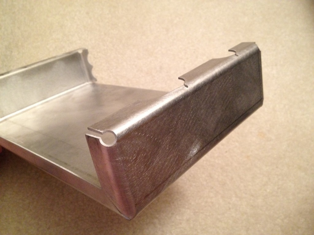
The two small holes in this part are defects from the water jet fabrication, not actual features in my model.
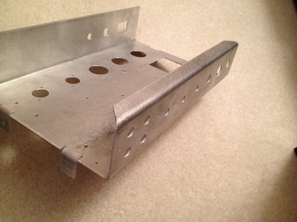
With this tooling mark, we can actually determine how to avoid the backing plate problem, which simplifies the fabrication of a one-off part considerably. The mark is .445 inches from the outside of the adjoining section, so the minimum safe bending flange length is .5 inches for my Aluminum 2024-T3 .062 thickness sheet at the minimum bend radius of 3/16″. Turns out, my 3/4″ flanges were a good safe length before cutting features out of them.

In the end, it took about two hours total to bend both parts, but it could have been twenty to thirty minutes if the flanges had been much simpler. I had been thinking that I wanted to the box to help shield circuit from RF noise as much as possible, but considering the old enclosure had negligible noise and negligible shielding the extra flanges are probably a waste.

Lessons Learned

  • Avoid features that are not perpendicular to the bend near the bend radius. This includes angles, holes, circular cutouts, and other assorted odd features. These features actually are permissible, but should really be machined into the flanges after bending if at all possible.
  • Make sure your flange lengths are long enough for the press brake to operate on them without a backing plate. This may be a guess in many cases, but a conservative guess is better than nothing.
  • Use the minimum bend radius for the material you are using, unless there is a specific need otherwise. Many less skilled operators will ignore the drawing and default to the minimum bend radius chart for bending their parts.
  • Call out every bend radius on your drawing. Do not leave these as a default, you might forget what you designed, or the operator may have to try and read your mind. If the operator uses the wrong die, your part will not come out the correct size and shape!
  • Call out every flange length length and wall size on your drawing directly. Use reference dimensions if this involves over-dimensioning the part. (Hmm, can you guess why I decided that was a good idea? Do you really want the brake operator to be doing math in order figure out to bend your part?) Forget about your high school drafting class exercises, nobody wants spend time doing that in industry, and it makes the fabricator mad at the designer for ignoring his needs.
  • Call out as many permutations of dimension on your flat pattern as you can think of, even if many of them are reference only. (Same thoughts as the previous bullet!)
  • Avoid designing so many flanges that you have flanges meeting at a corner. It is really not a big deal when you are getting a large number of the part fabricated because the brake operator can justify cutting a die to the appropriate length. Unfortunately, this is typically cost prohibitive for one-off jobs. I got lucky because the brake operator had some appropriate custom dies laying around from other volume jobs recently run in the shop.

One additional item worth mentioning: machine calibration is rarely perfect. My brake operator was able to bend my parts with almost extreme precision, but he had to set up each type of bend with 3 or 4 test attempts before attempting to brake the actual part. If the machine readout was perfect, then he could have just punched in the numbers and bent the part. The operator had experience with the machine, and knew not to trust the readout without testing it, so my parts were not ruined, but that is why you should put as many dimensions on the flat pattern and folded views as possible. You really do not want to force the brake operator to be guessing or doing math on your part, that is what engineering is for!

I know I mentioned this before, but I really cannot stress it enough, DIMENSION EVERYTHING! Most machinists or machine operators did not make quite the grades you did in their math classes, and even if they did, you are trusting someone else to figure out something that you already know. Don’t be stingy, just tell them and you will get your parts back faster and cheaper!

NOTE: In my case, the parts I designed were being fabricated on a press brake, using the air bending technique illustrated in the video and the bottom image on that wikipedia page. If you believe wikipedia, the Sheet Metal page has some additional info, indicating that the bend radius is a function of the width of the lower U-block, V-block, or Y-block, but my inner radius was 3/16″ and die radius used in the brake was also 3/16″.

Mar 132012
 

The Cyclonic Dust Separator project proposal won one of the 5 Seed Grants that were awarded this semester!  I will start really getting into this project next week, over spring break.  Here is the text of the email:


After slaving over the votes and grants, Dr. Forest and I have decided on five
grants for this semester. We favored the grants that contain many or all of the
following characteristics: Emphasizes invention and engineering over art; Supports
interdisciplinary design; Focuses on something new, not just a copy of something
that already exists.

The following five were chosen:

 1.     Photo Bioreactor - Blacki Milhose
 2.     Quadrotor - Justin Brotzman
 3.     Campanile-Climbing Robot - Will Borzon
 4.     Cyclonic Dust Separator - Sterling Peet
 5.     Tesla Coil - Chad Ramey

We will have a "Maker's Show and Tell Fair" at the end of the semester, where you'll
be encouraged to show off your creations, along with anyone else who would like to
show off what they made in the Invention Studio this semester.


For those of you who didn’t receive a grant: have no fear! We’ll be doing this again in the future, and we’ll be better at it then too. One of the problems with our first attempt was the generality with which the proposal guidelines were written – we’ll be more specific about what we want next time, and will hopefully have more grants to award as well.